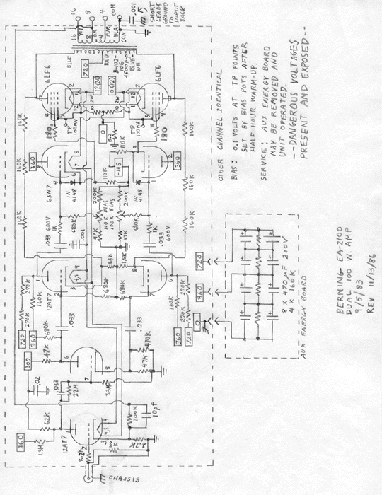
The 6LF6 output tubes have become extremely expensive and hard to find. The Svetlana EL509 is similar in characteristics, and with a substantial amount of work the EA-2100 can be changed to take these tubes. The socket must be changed, requiring a hole to be punched through the circuit board and the new socket to be mounted in the hole. All four tubes must be changed if this modification is attempted.
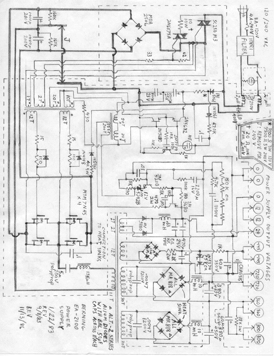
Failure prone parts in this amplifier are the triacs, 10-ohm 10 W soft-start resistor, and the power MOSFETs. These failures occurred early on, as the early MOSFETs had a poorer quality oxide than newer MOSFETs. For replacement purposes, see the schematic for the EA-2101 for newer types of MOSFETs. The TR6421M triac should be used in place of the obsolete SC250M3. Only two (one on each heat sink) of the IRF452s should be used (not four) if the MTM7N45s need to be replaced. The gate diodes and resistors are usually destroyed when the MOSFETs blow. A drop in power line voltage that sometimes occurs in a storm can destroy these parts. The added parts in the oscillator section shown in the schematic for the EA-2101: EC103B SCR, 2N5210 transistor, zener diodes, and other parts associated with these provides protection against low line voltage. These parts could be added to the EA-2100 if this is a recurring problem.
Early versions of this amp used two A114M (600V) diodes in series for each leg of the bridge instead of the single MR818 (1000V) diodes in the bridge rectifiers. These were prone to failure and a mod is to place 100pF-500V capacitors across each diode (16 in all required). If the change is made to single MR818s, heat sinks are required.
Bias measurements are taken across each of the 10-ohm, 2 W resistors that are located along the top edge of the audio boards. The correct voltage is 100mV.
Certain service to the audio boards requires the removal of the energy capacitor bank screwed to the backs of the audio boards. These unplug once the screws are removed, and the amp can be operated without these banks.
This amplifier should be able to put out at least 100 watts per channel.