|
Comparisons between the Berning ZOTL Impedance Converter
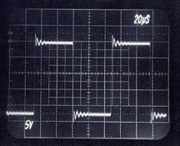
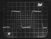
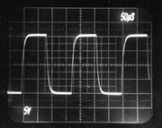
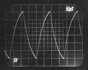
The following oscilloscope photos were taken to demonstrate the superiority of the Berning impedance converter over an high-quality audio-output transformer. Each pair of photos was taken when the same tube amplifier was coupled to the same resistive 8 Ohms load. The tube amplifier was a capacitively coupled unit with beam-type output tubes, and no feedback was used. The amplifier used a very common topology, but was designed for a wider bandwidth than normal for audio so that the speed of the impedance converter could be demonstrated. In both cases, the plate-to-plate loading was 5k Ohms and the effective turns ratio was the same for both the Berning converter and the transformer. This first pair of photos compares the Berning converter to the transformer using a 10kHz square wave. Notice that the rise time is significantly slower with the transformer (i.e., the leading edge, representing the higher frequencies, is sloped and not sharp). Also notice a lower-frequency component to the overshoot with the transformer.
Berning Converter- 10 kHz
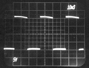
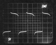
Transformer- 10 kHz This next pair of photos compares the Berning converter to the transformer using a 30Hz square wave. Notice the variable-slope tops and bottoms to the square wave with the transformer. This is a transformer-saturation effect. The deviation from perfect flatness with the Berning converter is due to a lack of stiffness in the power supply.
Berning Converter- 30 Hz
Transformer- 30 Hz This final pair of photos compares the Berning converter to the transformer under a special no-load condition using a 5kHz square wave. This test demonstrates a much lower parasitic capacitance associated with the Berning impedance converter than with the transformer. The transformer's capacitance comes from its necessarily large number of windings, and a dramatic loss of high-frequency information is evident. In the Berning converter, the high-frequency loss is much less. The high output impedance of the beam power tubes reacts with parasitic capacitance present in the plate circuit to determine frequency response for this no-load condition.
Berning Converter- 5 kHz, High impedance drive, no load.
Transformer- 5 kHz, High impedance drive, no load. |

