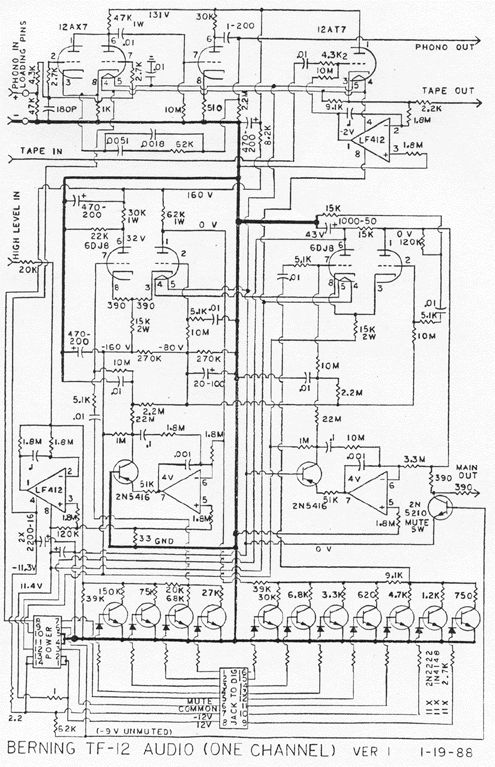
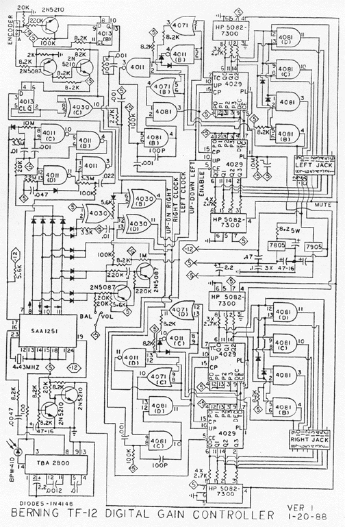
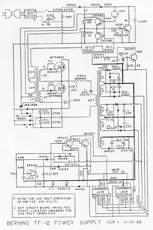
TF-12 Preamplifier
Tube pre-amplifier. Tube + FET hybrid technology.
Hybrid stereo preamplifier with remote control. Frequency response: high level +-1dB from 4Hz to 50kHz; phono within +-0.25dB of RIAA standard from 20Hz to 20kHz. Gain: high level 32dB; phono 32dB. Sensitivity: 0.6mV phono or 26mV high level for 1V out. Noise: Phono 60dB below 1mV in; high level 84dB below 1V. Input impedance: 47k ohms phono, 60k to 80k ohms high level, depending on volume setting. Output impedance: 3k ohms, tape and main. Max. input: Phono 200mV at 1kHz, high level 9V. Max. output: 6V. Harmonic distortion: 0.03% 2nd & 3rd, 0.002% 4th and above at 1kHz. Remote control: Infra-red, controls volume, channel balance, and mute. Power consumption: 40W. Dimensions: 19"W by 3-1/2"H by 13"D. Weight: 11 lbs. Price $2950.
TF-12 ReviewsThe Absolute Sound, vol. 70, March/April 1991, pp. 88
"The TF-12 delivered soundstage-creating performance at a truly spectacular level in my room, using two phono sources, Magnepan MG-III speakers, and three different amplifiers. For me, the Berning preamp has no superior in its ability to craft a large, no, a gigantic stage, and to place specific images in or on it with eerie focus and precision."
Stereophile, vol. 11, no. 7, July 1988, pp. 89
"The first thing I noticed about the TF-12's sound was its incredible liquidity. There is no spurious texturing whatsoever; the sound has all the limpid clarity of a dewdrop in the morning sun. It reproduces an impressively wide, spacious soundstage, while stage depth and front-to-back perspectives are rendered as well as from any preamp I've ever heard..."
TF-12 Support
The failure prone parts in the TF-12 are the optical encoder volume control, 1Meg resistor in the mute time out (located on the power supply board), the HER602 diodes in the power supply, 470 uF capacitors associated with these diodes, socket for 7805 voltage regulator IC on digital board (soldered in in later versions), and foil connections under tube sockets on the Teflon circuit board.
The failure of the optical encoder involves oxidation of the solder connections due to improper assembly by US Digital, in that the leads were cut too short. These controls can be pried open and these connections resoldered. Alternatively, a new control can be ordered from US Digital. http://www.usdigital.com Go to products tab, and then incremental encoders, and then look for the SP-16.
It is recommended that the HER602 diodes be replaced with the MUR820 (was Motorola, now ON Semiconductors), and that the 470 uF capacitors be upgraded to 1000 uF high-frequency types.
Loud pops, particularly in the phono section when the tubes are moved indicates broken foil on the circuit board. Thin foil traces should be bridged with light-gauge bare wire, even though the breaks can not be seen. Audio noise is sometimes caused by noisy 15K, 2W plate resistors on the 6DJ8/6922 tubes.


|
© 1974-2026 The David Berning Company
|
| |