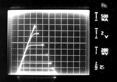
Electronic Devices and the Amplification Process The Berning ZH-270 is the first audio power amplifier that uses a new technology to properly match high-impedance vacuum tubes to low-impedance speakers. A full technical description of how the ZH amplifier works is beyond the scope of this short paper; however, the incentives that drove its development are described with the aid of curve-tracer photographs. Many who listen critically to audio amplifiers prefer the sound of vacuum tubes to the sound of solid-state amplifiers, and virtually all critical listeners agree that vacuum tube amplifiers sound different from solid-state amplifiers. In large part, the sonic characteristics of amplifiers can be correlated to the transfer characteristics of the amplifying devices used, and it is shown in this paper how output transformer hysteresis can significantly affect such characteristics. A curve tracer is an instrument that measures and displays the transfer characteristics of amplifying devices, and it can be used to aid in the design of amplifiers. Fig. 1 is a curve-tracer photograph showing the transfer characteristics of a triode-connected 6L6, with the plate connected to the screen grid, and driven with control grid voltage steps starting at 0 V and going to -100 V in 10 V increments. For each one of these grid-voltage steps the tube impedance is displayed by sweeping the plate voltage, and displaying it along with the resultant plate current. The curve tracer offers a selection of load resistors that limit the power to the tube, and these resistors can be used to establish a load line for the tube. The end points of all of the traces form an imaginary line, and in the case of fig.1, this is a 5k-ohm load line, and follows Ohm's Law which says that resistance equals voltage divided by current. The values of voltage and current that can be used in this formula can be obtained from fig.1 by observing that for each change of 100 V along the imaginary line in the horizontal direction there is a change of 20 mA in the vertical direction. The output resistance of the tube can also be determined at any particular operating point by imagining a line that is tangent to one of the constant grid-voltage lines displayed at the point of interest. Take for example the 300 V, 80 mA point crossed by the - 20 V line. A line tangent to this - 20 V grid line at this point represents a plate resistance of 50 V divided by 40 mA, or 1.25k ohms.
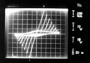
Fig. 1. Transfer characteristics of a triode-connected 6L6. In an amplifier, the load line is actually the load impedance that the tube is presented with to work against to move the speaker cone, and the plate resistance determines the damping qualities of the amplifier if feedback is not used. In a conventional tube amplifier, an output transformer is required to transform the 5k ohm load line needed by the tube to the 8 ohm load that the speaker imposes. The plate impedance is also transformed by the same ratio, so that in this case an output impedance of 2 ohms would be presented to the speaker for the 300 V, 80 mA operating point. The sonic character of amplifiers is influenced in large part by these impedances and how they interact with the speaker. Fig. 2 shows the transfer characteristics of a MOSFET transistor. One would expect that an amplifier built with these devices would sound quite unlike one built with the 6L6 tubes in the triode configuration. Pentode tube transfer curves (not shown) fall in between the triode and the transistor in general appearance, and this also correlates with their sonic characteristics.
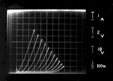
Fig. 2. MOSFET transfer characteristics. Load line 1.7 ohms; output resistance very high. Sonics aside, transistors have a big advantage over tubes in that they can operate directly into the load impedance presented by the speaker, whereas tubes need an impedance matching device like an output transformer. One could build an output transformer-less (OTL) amplifier out of parallel-connected, triode-configured 6L6 tubes. But a 50 watt amplifier needs to deliver about 4 amps peak current, requiring about 30 tubes for the push, and 30 more for the pull of a single channel push-pull amplifier. Our load line of 5k ohms would come down to one-thirtieth, or 167 ohms, still a bad impedance match for driving the speaker. The output impedance of such an amplifier might be a tenth of this value, depending on circuit configuration. Feedback could be used to lower the output impedance, but feedback would not change the load line. Fig. 3 shows what happens when a push-pull pair of triode-configured 6L6s are curve-traced through an output transformer with a 7 Hz to 50 kHz frequency response. The curve tracer is connected to the 16 ohm secondary and the plate winding is connected to the tube plates with the B+ tap grounded. In order to curve-trace through a transformer, the curve tracer must be set to operate in the ac mode, otherwise the dc component of the normal curve-tracing will saturate the core of the transformer. All of the previous descriptions of the various parameters can be applied to each half of this set of curves. The imposed load line is now 30 ohms for each tube, and the effective output impedance is about 15 ohms.
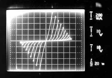
Fig. 3. Push-pull pair of 6L6s, triode-connected, and curve-traced through an output transformer. Some of the problems with output transformers are evident in these curves. The looping distortions of the constant grid-voltage lines is caused by magnetizing current, and the large horizontally oriented loop is the result of a mixture of the onset of core saturation and hysteresis, a major source of audible distortion. The Berning ZH amplifier performs the impedance matching function of the output transformer by applying special switching power supply technology. This technology (US patent 5,612,646) uses radio-frequency to change the tube transfer characteristics from their normal impedance plane to one suitable for driving a speaker. Because the audio impedance conversion is done with an RF carrier, it is not subject to the distortions imposed by the audio output transformer as shown in fig. 3. Fig. 4 shows the same triode-connected 6L6 curve traced through one implementation of the new Berning invention. Unlike the transformer, this impedance conversion works with the dc component of the curve-tracing, and it can be demonstrated with only one tube. Two tubes would still be required for a push-pull amplifier.
Fig. 4. Triode-connected 6L6 curve traced through the Berning impedance converter. Fig. 4 can be directly compared with fig. 1. Like an output transformer, the Berning impedance converter has a fixed ratio that can be thought of as a turns ratio. The converter used here has an effective turns ratio of 48 to 1. This is an unusually large ratio, and was used to demonstrate the flexibility of the technology. It is rare to find transformers that have more than a 13 to 1 ratio for each half of the push-pull because it is difficult to make them with good frequency response characteristics. In fig. 4 the imposed load line is 1.7 ohms and the effective plate (output) resistance at a sample effective operating point of 8 V, 5 A, and -20 grid volts, is 0.6 ohms. It is important to note that the tube is still operating with parameters similar to those imposed on it for the curve-tracing shown in fig.1, but the curve tracer sees the device shown in fig. 4. In an audio application, the tube behaves as if it is driving a 4k ohm speaker (the impedance conversion ratio goes as the square of the turns ratio), and the speaker acts and sounds as if it is being driven by a 0.6 ohm triode. Fig. 5 shows a push-pull pair of triode-connected 6L6s which are curve-traced through another implementation of the Berning invention. Again, the curve tracer is operating in the ac mode. For this demonstration, the effective turns ratio is 11.7 to 1 for each half of the impedance converter. This ratio closely matches the 11.2 to 1 per half ratio of the output transformer used for fig. 3. In comparing fig. 5 to fig. 3, it can be seen that the looping distortions are gone.
Fig. 5. Push-pull pair of 6L6s, triode-connected, and curve-traced through the Berning impedance converter. In conclusion, the Berning impedance converter can match vacuum tubes to speakers over a wide range of impedance-conversion ratios. The conversion is free of hysteresis distortions, can work in single-ended or push-pull applications, and works with both the ac and dc components of the signal. |